

Hi everyone! Thought I would try my hand at creating a comprehensive guide for replacing the lip seal on the cylinder position sensor on a 3g.
I'll start by saying I'm not trying to step on anyone's toes. I know there have been a couple of other posts regarding this, but unfortunately some of them are missing pictures and there isn't really a step-by-step guide available. So hopefully this will help some others.
For those who don't know, the Cyl sensor is located at the end of the exhaust cam and is next to the distributor. It is also known as the cylinder position sensor or cylinder number 1 position sensor. Its purpose is to report to the ECU what piston number one is doing by means of a simple magnetic pickup, rotor and 2 wires.
So with that out of the way lets get started:
Tools/Parts you will need:
Ratchet with 10mm and 7mm sockets or spanners of the same sizes
Philips head screwdriver (not too small)
Flat head screwdrivers, both small and large
Seal puller (recommended but not necessary)
Gasket maker/silicon
Cleaning chemicals (degreaser, brake clean, TB cleaner etc.)
Replacement lip seal (details below)
Replacement O-Ring (details below)
1. Removing the cyl sensor from the engine
Remove the plug and unbolt the sensor. This one is pretty self explanatory and kind of a test. If you can't do this step by yourself you may need some more practice or ask a friend for help before you continue any further and get stuck without a running car (This might seem harsh but it's for some peoples own good). The sensor is held on by 3x 10mm bolts, undo those and slide the sensor out gently.
2. Looking at the cyl sensor and unclipping the plug
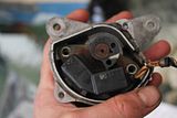
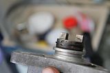
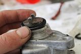
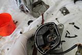
You should be looking at something similar to this now:
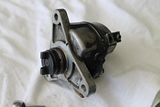
If you're not looking at something like this, put whatever you took off back on and call for help!
First up we will remove the plug from the metal clip. Slide a small screwdriver into the plastic plug. Moving the plastic lock up and out of the way. It's a bit hard to get a pic but hopefully this will give you a good idea:
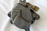
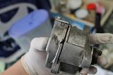
3. Removing the sensor cap
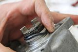
Remove the 2 bolts holding the sensor cap on. You may use a philips head screwdriver but a 7mm socket is highly recommended for these as they can strip easily.
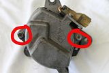
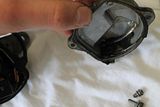
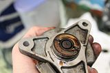
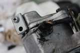
Once the bolts are out. Hold the cap firmly and wiggle it until it pulls free. If it is stuck you can use a large flat head screwdriver to help push it open using one of the caps protruding pieces. DO NOT stick a screw driver in between the cap and the housing, you risk damaging the gasket surface.
As you can see by the inside of the cap this unit has definitely been leaking oil internally.
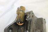
4. Marking our position
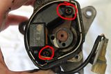
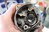
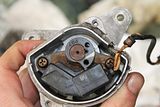
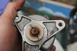
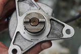
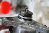
Once it has been pried apart you should be greeted by the internals of the cyl sensor. There's that magnetic pickup. You can try spinning the shaft and looking at how it operates if you like learning new things.
Before continuing any further you will need to mark the position of the shaft and the coupling so it goes back on the right way. Line up the magnetic pickup with the rotor as so:
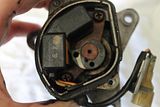
Now look at the other end of the sensor and mark which way the coupling should go back on. I have used a black line. Now I know that when it all goes back together, the line on the coupling should be on the same side as my mark I just made.
I am not sure of the consequences of putting the couple on 180 degrees, but I'm not game to try it.
5. Removing the magnetic pickup screws
Using a largeish philips head screwdriver remove the two screws holding down the plate that the magnetic pickup is on. Being careful not to damage the wires.
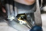
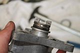
6. Removing the coupling and roller pin
On the other side of the unit we will now take off the coupling. Look at the wire retainer and find the break in it (I recommend rotating it around to the hole for the roller so you can get a better go at it), using a small flat head screw drivers get in between the unit and the retainer and pry it away while lifting up.
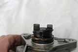
Keep working your way around the whole retainer until you can pop it off.
The pin inside the unit is the last bit holding the coupling on. Using a small screwdriver, gently push it out of the hole.
The coupling will now pull off the shaft. Behind the coupling (or stuck to it) will be one or two small shims. Do not lose these, put them aside with the coupling.
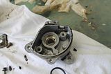
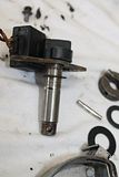
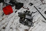
7. Removing the assembly from the housing.
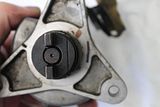
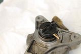
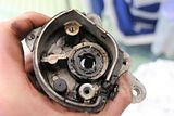
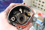
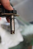
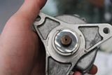
The entire shaft and assembly is now free to be removed from the housing. Pushing from the base, like this:
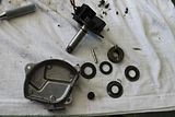
You should be able to remove the entire assembly and be left with something like this:
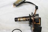
and this:
Be careful of the washer still on the shaft. You may take it off and put it aside, but do not lose it. Also take note of the small rubber cap towards the left of the unit in that last picture, it can pop off easily and you don't want to lose it.
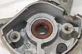
8. Removing the last washer and the lip seal.
Holding the seal in place is a large washer that is in turn being kept there by some claw like parts of the housing. Getting it out can be difficult. Because I won't be reusing the seal I have used a large flat head screwdriver to hit the base of the washer and pop it free as per this pic:
Holding it in place and at an angle you can tap the base of the screwdriver on the ground to pop the washer free. You must be careful when inserting the screwdriver not to damage the cylinder that the shaft slides into.
It should hopefully pop off something like this:
Now, underneath that washer is the lip seal we're going to all this trouble to remove! Take note that the writing on the seal is facing you, the new seal must go the same way.
They can get quite tough with age so they can be a pain to remove! So I recommend a seal puller:

If you do not have access to one of these you can persevere with the screwdriver trick for removing the washer. Again, being careful not to damage any of the housing.
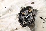
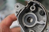
Tada:
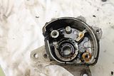
One empty housing.
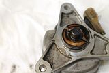
9. Clean the housing and the shaft.
Lots of crusty oil built up over the years leaves quite a mess! I used a combination of degreaser and throttle body cleaner with a tooth brush and rag to clean the majority of it. Brake cleaner etc. should also work effectively. I recommend removing that rubber cap that we looked at in step 7 as it will not approve of chemicals.
You can wipe the magnetic pickup and rotor etc with a rag but be careful with the cleaning products, I am not sure what affect they may or may not have.
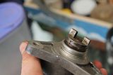
Now lets have a look at the shaft after giving it a clean. Notice the extra shiny bits. This is where the old seal has worn a groove into it. You can feel quite a nasty indent with your fingernail. This will affect my seal choice later on, so you may wish to inspect this carefully.
10. Replacing the seal and washer
The original seal is an NOK with part number W0133-1640599. I recommend replacing with this or another high quality substitute, you don't really want to be doing this again. In contradiction to this though, here is my $4 seal .
.
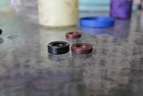
Notice the height difference, there is a reason for this! I picked a shorter seal on purpose. Remember in step 9 I showed the damage to the shaft made by the old seal. Using an identical seal I risk still leaking oil because the surface is too worn for even a new seal to stop leaks. The shorter seal will be sealing on a different part of the shaft, a part that hasn't been damaged, so in theory, will work perfectly.
Add a little bit of grease or Vaseline to the inside of the seal. This will help to make sure the seal isn't destroyed before the oil reaches it on first start up.
Push the seal into the housing with the face (the bit with the writing) towards you. Be gentle and work your way around the seal. If you find it too tight, add a little bit of grease or Vaseline to the outside. Push the seal in until it is flush with bottom lip of the housing (below where that washer sits) Like this:
If you're using an original full size seal, keep pushing until it's fully inserted. The NOK seal will seat on the base.
Were now going to put that washer back into it's home. Place it back in as much as you can, you will probably have one side sitting out (unless you've got strong fingers!). Using a piece of wood or something that gives a little bit, you can tap it back in (use a small hammer on top the wood if absolutely necessary).
Once quick tap and it should hopefully pop back into place like this!
11. Putting the guts back in
We're now just about ready to put the shaft back inside the unit. Before doing that though, add a little bit of grease or Vaseline to the shaft to help it slide through the seal without damaging it and this will also help it on first start up.
Put that second washer back on as well! Wouldn't work well if you left that off! The shaft should hopefully look something like this!
Now slide the bottom of the shaft (the bit where the coupling normally is) through the top of the unit. Gently, we don't want to damage our new seal. If it's too tight, add a little bit more grease and try again. Rotating the shaft slightly as you slide it in can also help. (Man, this sounds dirty). Keep in mind we are actually pushing the shaft the wrong way through the lip seal so gentle is best!
Once it's all the way through it should look something like this!
Put the screws back in, but do not do them up full tight just yet.
Also in that last pic make sure the wires are coming out the cutout made for them. We don't want to pinch them later on.
One last thing before we move on, rotate the shaft a little bit, making sure it's freely moving and once you're done, line the rotor up again with the magnetic pickup.
12. Attaching the coupling.
Onto the other side of the sensor. It will look something like this.
Place the shims onto the unit
Now put the coupling on top. Line it up with the mark we made earlier on and make sure the holes are also lined up.
Slide the roller pin back into the unit. It should go in much easier than it was to get out, now that it's all cleaned up!
Push the retainer on in exactly the opposite way you took it off. Start at one end and work around the retainer until it pops back into its groove.
The coupling should now be held in place! Double check that line and mark you just made while you're here!
13. Gapping the rotor
Back in step 12 we didn't do those screws up all the way (If you did do them up, undo them slightly now). The reason for that is we need to get the proper gap between the rotor and the magnetic pickup for it to work at it's best.
The pic I will be using is from the workshop manual (Lazy me!)
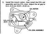
Using a feeler gauge make sure the gap between the rotor and the pickup is between 0.3-0.5mm. Then tighten those two screws so the unit doesn't move!
I'm not going to lie, the reason I don't have a picture for this is because I forgot to do this before I'd finished assembling the unitmg:. I will pull it back apart later and re-do this step with more detail.
14. Replacing the outer o-ring.
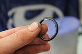
Can't forget this little guy. This keeps the seal between the entire CYL sensor unit and the head. If your seal is anything like mine it's probably majorly plasticized and easy to remove with a small screwdriver (delicately). The O-ring is Honda part number 30110-PA1-732 or equivalent 26.4x3.1 O-ring.
To put the new o-ring on first lube it up with some Vaseline or grease and then start sliding it onto the unit slowly.
Start pushing it slowly around the entire seal, bit by bit
Until you're able to push the entire seal into it's groove.
15. Replacing the cap and new gasket
Nearly there everyone!
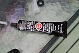
We're just about ready to replace the cap. But before we do that. I'm going to take a stab in the dark and say that you're old outer gasket is nearly destroyed and made of rock. Unfortunately I've not been able to source a replacement gasket/seal for the cap so I will be making a new one with gasket maker.
Fortunately this seal is only too keep moisture out of the unit and is not an oil seal. This is my weapon of choice for the new seal but most gasket makers should do the job.
Make sure all the old gasket is removed and lay a bead of new gasket maker around the unit like so:
Pay special attention to where the wires come out of the unit. There is normally a special seal that holds the wires in place but mine had perished. If yours is still in tact you may wish to use that. Otherwise make sure there is gasket goo both below and above the wires.
Push the cap back onto the unit carefully. You should hopefully see a little bit of gasket goo being pushed out (but not too much!)
Put those 2 7mm bolts back in and do them up. Clean the excess gasket maker off with a rag.
You may need to apply some extra gasket maker around those wires. Once you're done it might look something like this (maybe tidier!)
That teeny metal bracket that sits around the 2 wires should be completely outside of the unit and does not make up part of the seal.
16. Now we wait and then reattach the plug
My particular gasket maker is required to sit for 24 hours before use. Yours maybe different. Always follow the instructions on the packaging, if you use it too soon the gasket/seal may fail. Don't hesitate to add a little extra gasket maker in parts you think may not be sealing correctly we want it to be as water tight as possible.
Once the seal has cured the plug is ready for reattachment. Clip the wires back onto the metal bracket and screw that onto the unit again. Use this picture for reference. Note the orientation of the bracket and the wires running underneath:
17. Almost done
The moment of truth. Reattach the unit to the head. I recommend a little bit extra grease/Vaseline on the o-ring as she will be tight. Before sliding the unit on note the orientation of the cam shaft and turn the coupling on the CYL sensor to match.
The coupling is offset to one side, so the unit can only go on one way. If you're finding it far too difficult to slide into the cam, the O-ring may need more lube or it's possible you have oriented the coupling 180 degrees. Double check this, you definitely don't want to put it on backwards (It is only possible with force!)
Put the 3 10mm bolts back in and tighten to ~12nm. Make sure to do them up evenly just like you would with wheel nuts. The attach the wiring plug.
Cross your fingers and start the car. If all went well, the car should start no problems! Check for any engine light relating to the CYL sensor. And over the coming days/weeks periodically check for any oil leaks.
Fin
If there any issues, bits missing or mistakes with this guide, please let me know so I can fix them up asap! This guide took me a while to put together so hopefully it can be useful for people who don't want to have to replace their entire CYL sensor as per Honda's recommendation. As I said before, I recognise other peoples work previously on this topic, I was just hoping to make a more comprehensive guide and I mean no disrespect to others.
Thanks everyone,
Lorby
I'll start by saying I'm not trying to step on anyone's toes. I know there have been a couple of other posts regarding this, but unfortunately some of them are missing pictures and there isn't really a step-by-step guide available. So hopefully this will help some others.
For those who don't know, the Cyl sensor is located at the end of the exhaust cam and is next to the distributor. It is also known as the cylinder position sensor or cylinder number 1 position sensor. Its purpose is to report to the ECU what piston number one is doing by means of a simple magnetic pickup, rotor and 2 wires.
So with that out of the way lets get started:
Tools/Parts you will need:
Ratchet with 10mm and 7mm sockets or spanners of the same sizes
Philips head screwdriver (not too small)
Flat head screwdrivers, both small and large
Seal puller (recommended but not necessary)
Gasket maker/silicon
Cleaning chemicals (degreaser, brake clean, TB cleaner etc.)
Replacement lip seal (details below)
Replacement O-Ring (details below)
1. Removing the cyl sensor from the engine
Remove the plug and unbolt the sensor. This one is pretty self explanatory and kind of a test. If you can't do this step by yourself you may need some more practice or ask a friend for help before you continue any further and get stuck without a running car (This might seem harsh but it's for some peoples own good). The sensor is held on by 3x 10mm bolts, undo those and slide the sensor out gently.
2. Looking at the cyl sensor and unclipping the plug
You should be looking at something similar to this now:


If you're not looking at something like this, put whatever you took off back on and call for help!
First up we will remove the plug from the metal clip. Slide a small screwdriver into the plastic plug. Moving the plastic lock up and out of the way. It's a bit hard to get a pic but hopefully this will give you a good idea:


3. Removing the sensor cap
Remove the 2 bolts holding the sensor cap on. You may use a philips head screwdriver but a 7mm socket is highly recommended for these as they can strip easily.

Once the bolts are out. Hold the cap firmly and wiggle it until it pulls free. If it is stuck you can use a large flat head screwdriver to help push it open using one of the caps protruding pieces. DO NOT stick a screw driver in between the cap and the housing, you risk damaging the gasket surface.
As you can see by the inside of the cap this unit has definitely been leaking oil internally.

4. Marking our position
Once it has been pried apart you should be greeted by the internals of the cyl sensor. There's that magnetic pickup. You can try spinning the shaft and looking at how it operates if you like learning new things.
Before continuing any further you will need to mark the position of the shaft and the coupling so it goes back on the right way. Line up the magnetic pickup with the rotor as so:

Now look at the other end of the sensor and mark which way the coupling should go back on. I have used a black line. Now I know that when it all goes back together, the line on the coupling should be on the same side as my mark I just made.

I am not sure of the consequences of putting the couple on 180 degrees, but I'm not game to try it.
5. Removing the magnetic pickup screws
Using a largeish philips head screwdriver remove the two screws holding down the plate that the magnetic pickup is on. Being careful not to damage the wires.

6. Removing the coupling and roller pin
On the other side of the unit we will now take off the coupling. Look at the wire retainer and find the break in it (I recommend rotating it around to the hole for the roller so you can get a better go at it), using a small flat head screw drivers get in between the unit and the retainer and pry it away while lifting up.

Keep working your way around the whole retainer until you can pop it off.
The pin inside the unit is the last bit holding the coupling on. Using a small screwdriver, gently push it out of the hole.

The coupling will now pull off the shaft. Behind the coupling (or stuck to it) will be one or two small shims. Do not lose these, put them aside with the coupling.
7. Removing the assembly from the housing.
The entire shaft and assembly is now free to be removed from the housing. Pushing from the base, like this:


You should be able to remove the entire assembly and be left with something like this:

and this:

Be careful of the washer still on the shaft. You may take it off and put it aside, but do not lose it. Also take note of the small rubber cap towards the left of the unit in that last picture, it can pop off easily and you don't want to lose it.
8. Removing the last washer and the lip seal.
Holding the seal in place is a large washer that is in turn being kept there by some claw like parts of the housing. Getting it out can be difficult. Because I won't be reusing the seal I have used a large flat head screwdriver to hit the base of the washer and pop it free as per this pic:

Holding it in place and at an angle you can tap the base of the screwdriver on the ground to pop the washer free. You must be careful when inserting the screwdriver not to damage the cylinder that the shaft slides into.
It should hopefully pop off something like this:

Now, underneath that washer is the lip seal we're going to all this trouble to remove! Take note that the writing on the seal is facing you, the new seal must go the same way.

They can get quite tough with age so they can be a pain to remove! So I recommend a seal puller:

If you do not have access to one of these you can persevere with the screwdriver trick for removing the washer. Again, being careful not to damage any of the housing.
Tada:

One empty housing.
9. Clean the housing and the shaft.
Lots of crusty oil built up over the years leaves quite a mess! I used a combination of degreaser and throttle body cleaner with a tooth brush and rag to clean the majority of it. Brake cleaner etc. should also work effectively. I recommend removing that rubber cap that we looked at in step 7 as it will not approve of chemicals.
You can wipe the magnetic pickup and rotor etc with a rag but be careful with the cleaning products, I am not sure what affect they may or may not have.


Now lets have a look at the shaft after giving it a clean. Notice the extra shiny bits. This is where the old seal has worn a groove into it. You can feel quite a nasty indent with your fingernail. This will affect my seal choice later on, so you may wish to inspect this carefully.

10. Replacing the seal and washer
The original seal is an NOK with part number W0133-1640599. I recommend replacing with this or another high quality substitute, you don't really want to be doing this again. In contradiction to this though, here is my $4 seal
.
Notice the height difference, there is a reason for this! I picked a shorter seal on purpose. Remember in step 9 I showed the damage to the shaft made by the old seal. Using an identical seal I risk still leaking oil because the surface is too worn for even a new seal to stop leaks. The shorter seal will be sealing on a different part of the shaft, a part that hasn't been damaged, so in theory, will work perfectly.
Add a little bit of grease or Vaseline to the inside of the seal. This will help to make sure the seal isn't destroyed before the oil reaches it on first start up.
Push the seal into the housing with the face (the bit with the writing) towards you. Be gentle and work your way around the seal. If you find it too tight, add a little bit of grease or Vaseline to the outside. Push the seal in until it is flush with bottom lip of the housing (below where that washer sits) Like this:

If you're using an original full size seal, keep pushing until it's fully inserted. The NOK seal will seat on the base.
Were now going to put that washer back into it's home. Place it back in as much as you can, you will probably have one side sitting out (unless you've got strong fingers!). Using a piece of wood or something that gives a little bit, you can tap it back in (use a small hammer on top the wood if absolutely necessary).
Once quick tap and it should hopefully pop back into place like this!

11. Putting the guts back in
We're now just about ready to put the shaft back inside the unit. Before doing that though, add a little bit of grease or Vaseline to the shaft to help it slide through the seal without damaging it and this will also help it on first start up.
Put that second washer back on as well! Wouldn't work well if you left that off! The shaft should hopefully look something like this!

Now slide the bottom of the shaft (the bit where the coupling normally is) through the top of the unit. Gently, we don't want to damage our new seal. If it's too tight, add a little bit more grease and try again. Rotating the shaft slightly as you slide it in can also help. (Man, this sounds dirty). Keep in mind we are actually pushing the shaft the wrong way through the lip seal so gentle is best!
Once it's all the way through it should look something like this!

Put the screws back in, but do not do them up full tight just yet.

Also in that last pic make sure the wires are coming out the cutout made for them. We don't want to pinch them later on.
One last thing before we move on, rotate the shaft a little bit, making sure it's freely moving and once you're done, line the rotor up again with the magnetic pickup.
12. Attaching the coupling.
Onto the other side of the sensor. It will look something like this.

Place the shims onto the unit

Now put the coupling on top. Line it up with the mark we made earlier on and make sure the holes are also lined up.

Slide the roller pin back into the unit. It should go in much easier than it was to get out, now that it's all cleaned up!

Push the retainer on in exactly the opposite way you took it off. Start at one end and work around the retainer until it pops back into its groove.

The coupling should now be held in place! Double check that line and mark you just made while you're here!

13. Gapping the rotor
Back in step 12 we didn't do those screws up all the way (If you did do them up, undo them slightly now). The reason for that is we need to get the proper gap between the rotor and the magnetic pickup for it to work at it's best.
The pic I will be using is from the workshop manual (Lazy me!)

Using a feeler gauge make sure the gap between the rotor and the pickup is between 0.3-0.5mm. Then tighten those two screws so the unit doesn't move!
I'm not going to lie, the reason I don't have a picture for this is because I forgot to do this before I'd finished assembling the unit
mg:. I will pull it back apart later and re-do this step with more detail.14. Replacing the outer o-ring.
Can't forget this little guy. This keeps the seal between the entire CYL sensor unit and the head. If your seal is anything like mine it's probably majorly plasticized and easy to remove with a small screwdriver (delicately). The O-ring is Honda part number 30110-PA1-732 or equivalent 26.4x3.1 O-ring.
To put the new o-ring on first lube it up with some Vaseline or grease and then start sliding it onto the unit slowly.


Start pushing it slowly around the entire seal, bit by bit

Until you're able to push the entire seal into it's groove.

15. Replacing the cap and new gasket
Nearly there everyone!
We're just about ready to replace the cap. But before we do that. I'm going to take a stab in the dark and say that you're old outer gasket is nearly destroyed and made of rock. Unfortunately I've not been able to source a replacement gasket/seal for the cap so I will be making a new one with gasket maker.
Fortunately this seal is only too keep moisture out of the unit and is not an oil seal. This is my weapon of choice for the new seal but most gasket makers should do the job.

Make sure all the old gasket is removed and lay a bead of new gasket maker around the unit like so:

Pay special attention to where the wires come out of the unit. There is normally a special seal that holds the wires in place but mine had perished
. If yours is still in tact you may wish to use that. Otherwise make sure there is gasket goo both below and above the wires.Push the cap back onto the unit carefully. You should hopefully see a little bit of gasket goo being pushed out (but not too much!)

Put those 2 7mm bolts back in and do them up. Clean the excess gasket maker off with a rag.
You may need to apply some extra gasket maker around those wires. Once you're done it might look something like this (maybe tidier!)

That teeny metal bracket that sits around the 2 wires should be completely outside of the unit and does not make up part of the seal.
16. Now we wait and then reattach the plug
My particular gasket maker is required to sit for 24 hours before use. Yours maybe different. Always follow the instructions on the packaging, if you use it too soon the gasket/seal may fail. Don't hesitate to add a little extra gasket maker in parts you think may not be sealing correctly we want it to be as water tight as possible.
Once the seal has cured the plug is ready for reattachment. Clip the wires back onto the metal bracket and screw that onto the unit again. Use this picture for reference. Note the orientation of the bracket and the wires running underneath:

17. Almost done
The moment of truth. Reattach the unit to the head. I recommend a little bit extra grease/Vaseline on the o-ring as she will be tight. Before sliding the unit on note the orientation of the cam shaft and turn the coupling on the CYL sensor to match.
The coupling is offset to one side, so the unit can only go on one way. If you're finding it far too difficult to slide into the cam, the O-ring may need more lube or it's possible you have oriented the coupling 180 degrees. Double check this, you definitely don't want to put it on backwards (It is only possible with force!)
Put the 3 10mm bolts back in and tighten to ~12nm. Make sure to do them up evenly just like you would with wheel nuts. The attach the wiring plug.
Cross your fingers and start the car
. If all went well, the car should start no problems! Check for any engine light relating to the CYL sensor. And over the coming days/weeks periodically check for any oil leaks.Fin
If there any issues, bits missing or mistakes with this guide, please let me know so I can fix them up asap! This guide took me a while to put together so hopefully it can be useful for people who don't want to have to replace their entire CYL sensor as per Honda's recommendation. As I said before, I recognise other peoples work previously on this topic, I was just hoping to make a more comprehensive guide and I mean no disrespect to others.
Thanks everyone,
Lorby