
This is general information of wire locations + functions that will be very useful if you are trying to wire in an engine harness that uses a flying lead. Basically these are the wires you should tap to interface whichever engine harness + ECU you are using to the chassis harness.
I tap into these connector block wires instead of the ECU plugs because they are OBD/year agnostic. The wire locations and colors shown here are the same for all fuel-injected 3g Preludes no matter if the ECU was OBD0 or OBD1.
One warning though; I have only verified this with left hand drive cars. If you successfully use these instructions to wire a RHD car please let me know.
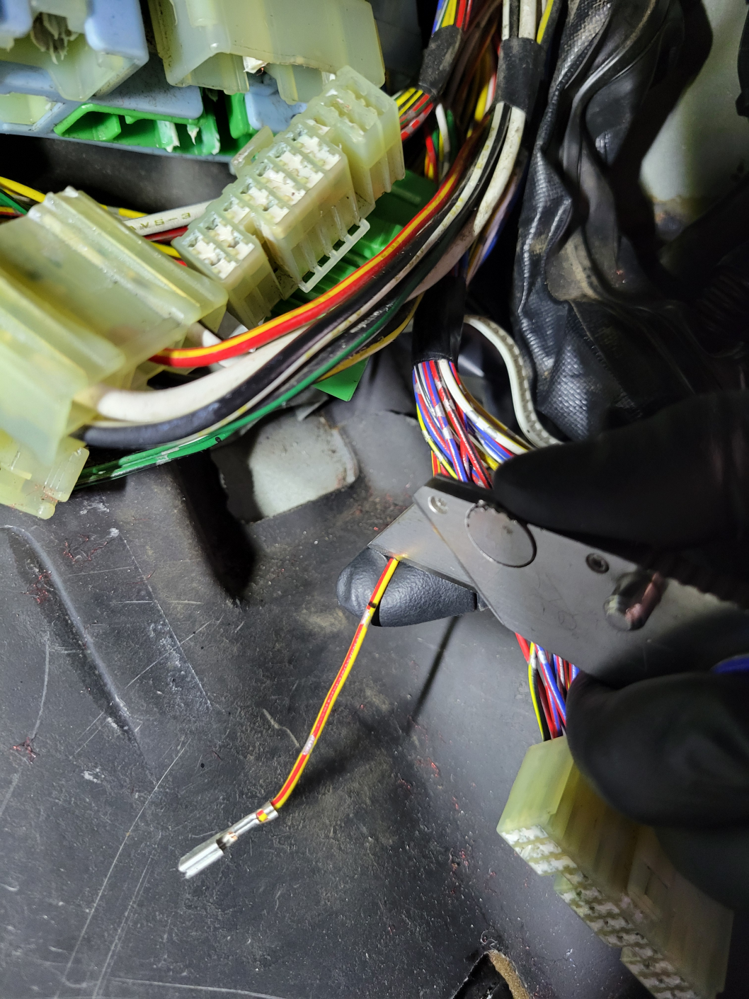
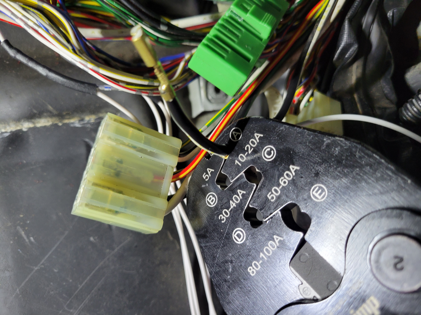
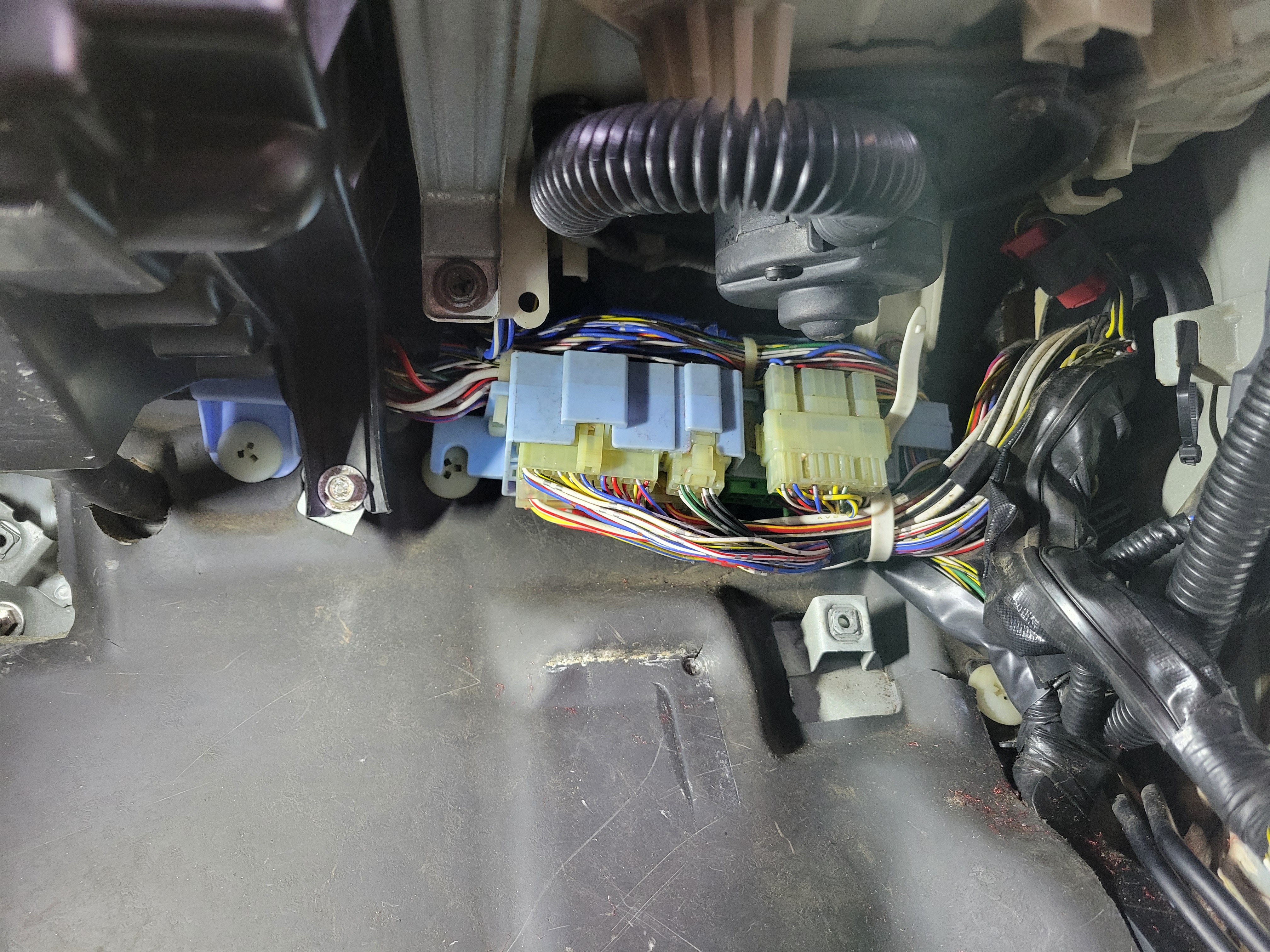
The connector block is under the blower. Undo the white "zip tie" on the right using a small flathead then disconnect the connectors:
![Image]()
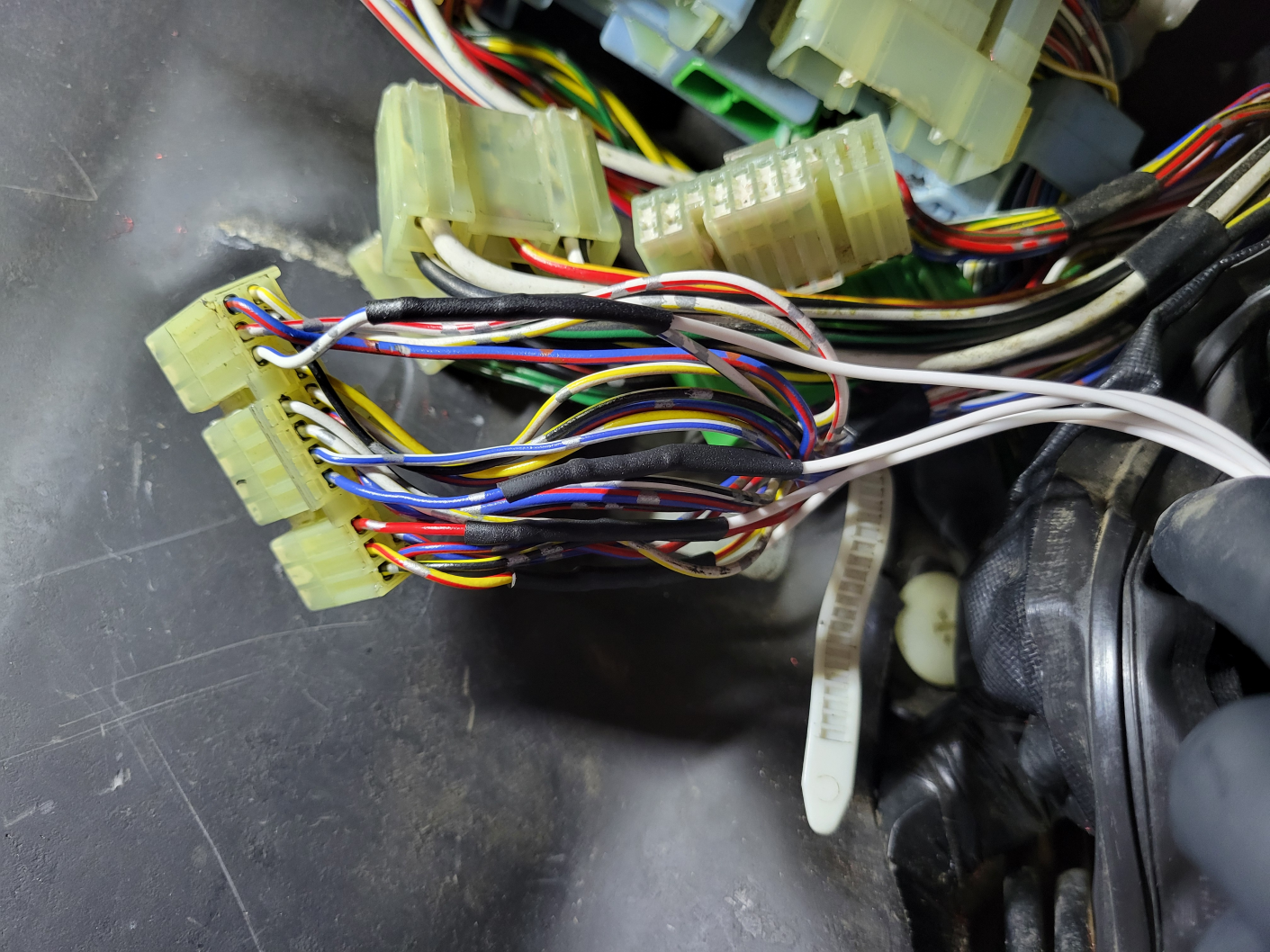
Here is the connector numbering:

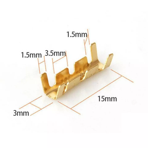
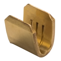
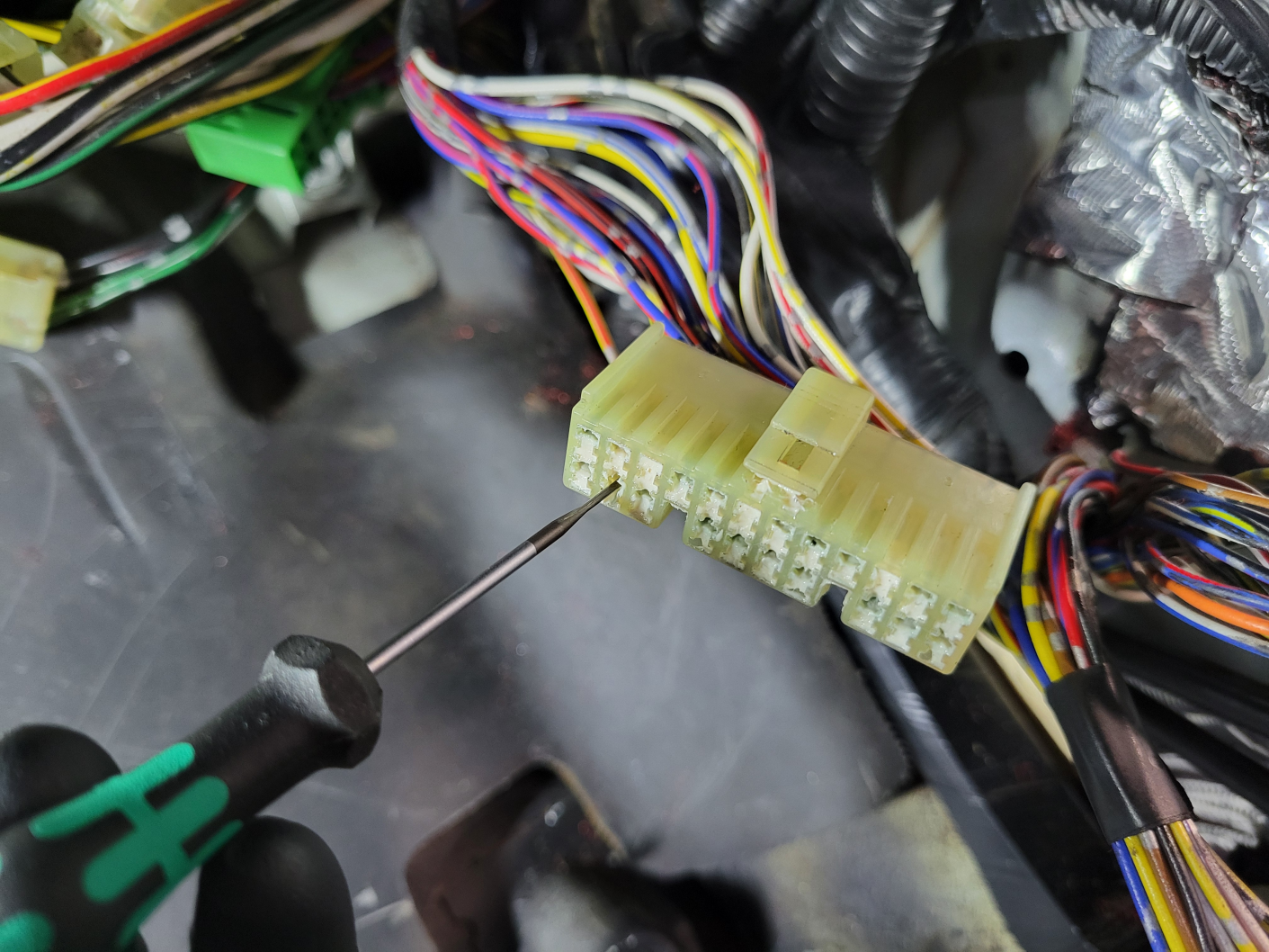
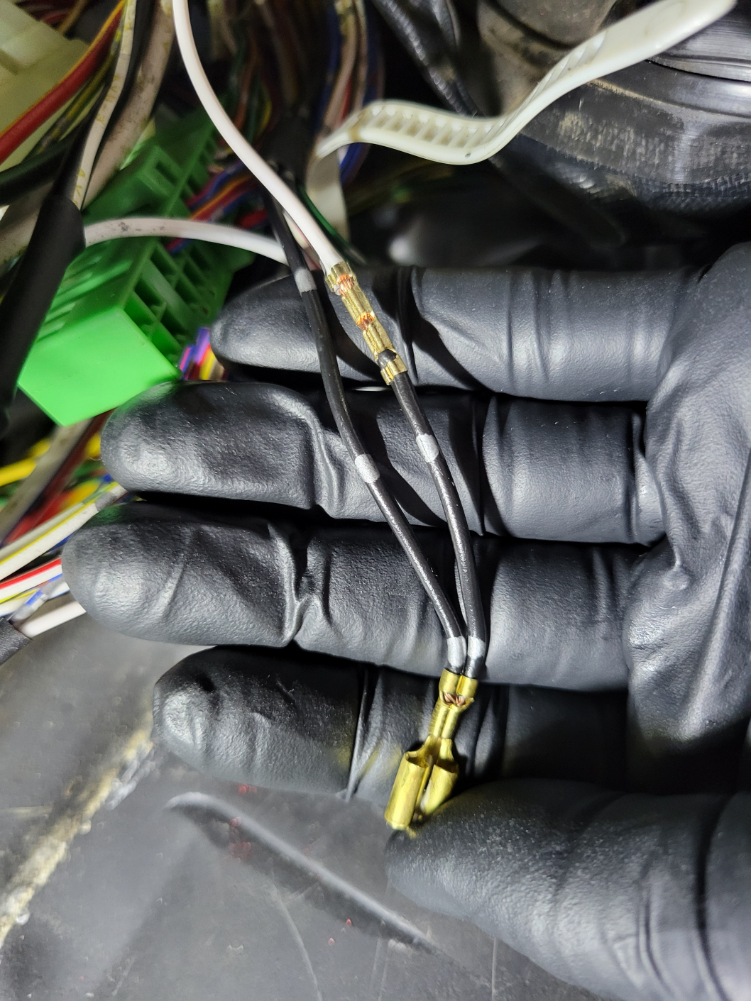
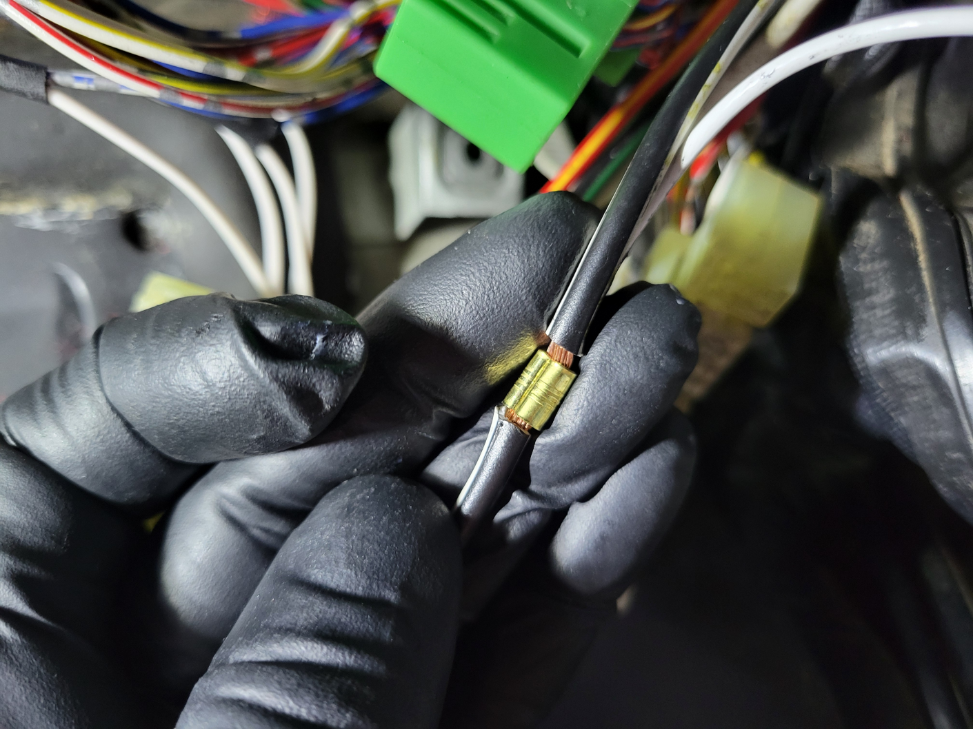
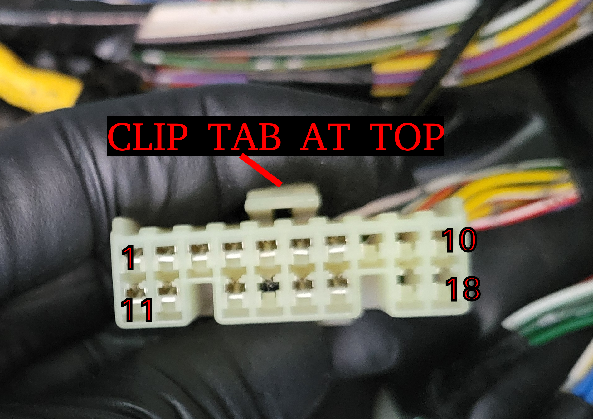
We will be working with these male connectors. The pin ordering on these male connectors is done looking into the terminal side, the opposite side as the wires. The clip tab will be at the top and the pins are numbered left to right starting in the top left, example:
![Image]()
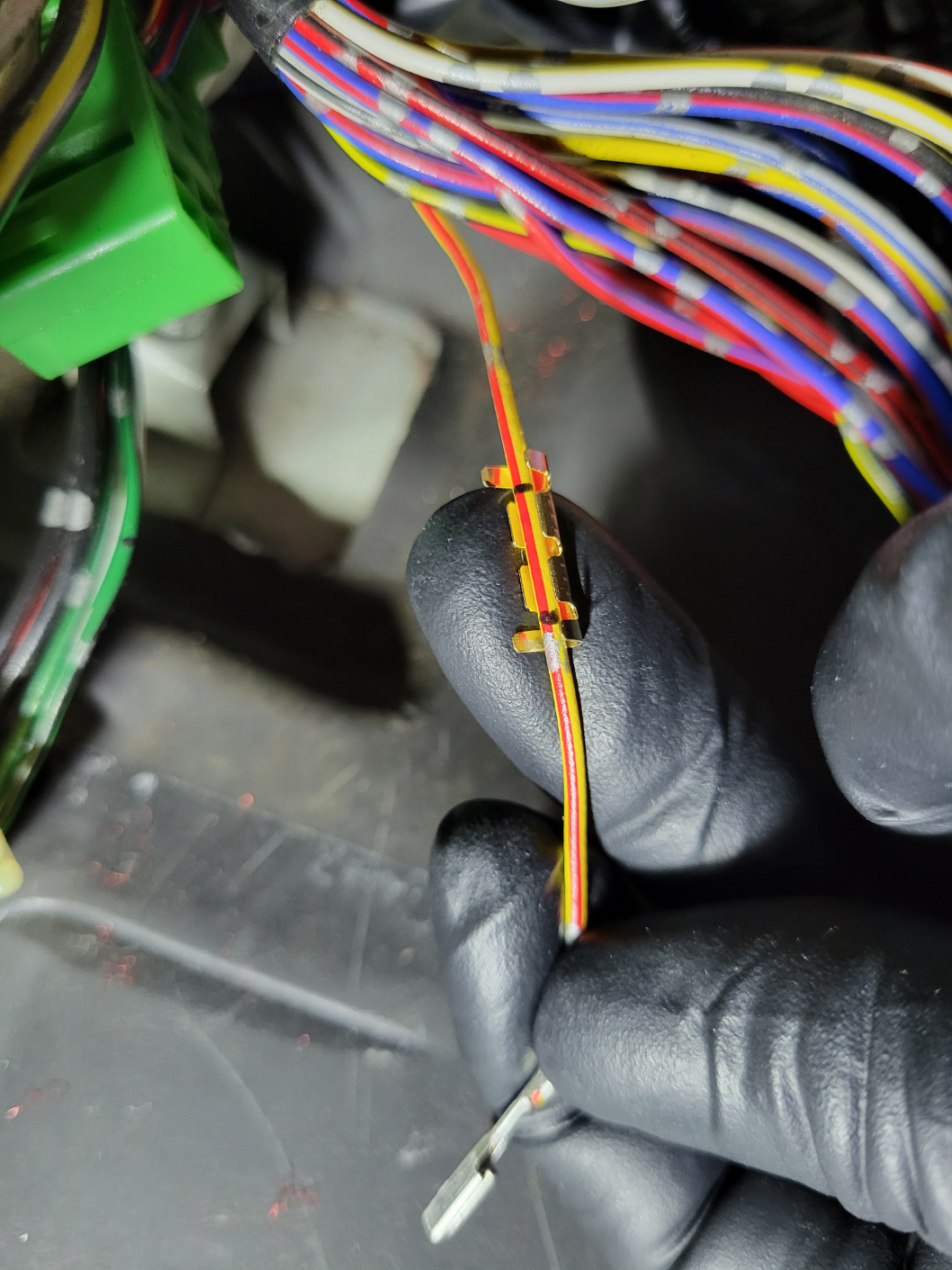
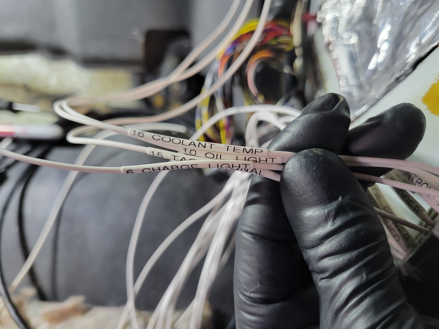
Wires are labeled with abbreviated color names, example:
Black = BLK
Blue = BLU
Red = RED
White = WHT
Yellow = YEL
Etc.
Striped wires are always labeled with the primary color first then the stripe color next. So a black wire with a red stripe would be:
BLK/RED
Here are the connectors and pins that you can use for various things depending on what exactly you are wiring:
C258 (4-PINS):
1: BLK - Main relay ground
2: GRN/BLK - Fuel relay ground
C259 (22-PINS):
9: YEL - Reverse switch 12V (IMPORTANT: 90-91 ONLY)
12: WHT/YEL- 12V 10a constant CLOCK fuse (memory)
14: YEL/RED - Oil pressure warning light
15: RED - Engine coolant temperature (gauge)
16: BLU - Tachometer signal
17: WHT/BLU - Charge warning light
C260 (23-PINS):
9: BLU/RED - Starter signal
15: YEL - Reverse switch 12V (IMPORTANT: 88-89 ONLY)
16: GRN/BLK - Reverse switch to bulbs
C262 (7-PINS):
1: BLK/WHT - Starter trigger
C263 (18-PINS):
3: YEL/BLK - ECU power from main relay
5: YEL/RED - MIL / Check engine light
6: WHT/BLU - Speedometer pulse
13: BLU/RED - Power steering switch
I will go into more detail about these wires and how you might/should use them:
--------
C258:
#1 BLK: This is the ground wire that comes off the main relay. In OE form this grounds to G101, at the thermostat housing. It does not need to be grounded there specifically, but if you change out the OE harness you must ground this somewhere or the main relay will not work. This is a critical ground make sure it is well grounded.
#2 GRN/BLK: This is the ground wire for the fuel pump relay (inside the main relay). If you ground this while the main relay is powered the fuel pump will turn on. In OE form this will be wired to the "FLR" aka. "Fuel Relay" pins at an OBD1 ECU.
For crash safety this should NOT be hard wired to ground. It should be wired to whichever ECU you use, so that the ECU can turn off the fuel pump if the engine stops (by switching ground). The OE setup is like this so that if you are in a bad crash which severs a fuel line the ECU will kill the pump once the engine dies, rather than continuing to pump fuel (out of the severed line).
--------
C259:
#9 YEL: 90-91 ONLY. This is the 12V supply to the reverse switch on the transmission. Wire it to either pin on the reverse switch.
#12 WHT/YEL: This is a constant (key off) 12v 10amp memory coming from the CLOCK fuse in the under hood fuse box.
#14 YEL/RED: This is for the low oil pressure warning light in the cluster. If you ground this while the key is on the warning light should illuminate. Wire it to the single wire oil pressure switch on the engine.
#15 RED: This is for the coolant temperature gauge in the cluster. It is for the cluster only, DO NOT WIRE IT TO THE ECU. Wire it to the single wire coolant sensor on the engine.
#16 BLU: This is the tachometer signal to the gauge in the cluster. Depending on your setup the tach wire from the engine harness might branch, one going to the ECU and one going here to the cluster. Alternatively there might just be a tachometer wire coming directly from the ECU that you will wire to this.
#17 WHT/BLU: This is for the battery charge warning light in the cluster. Also known as ALT-L, in OE form this goes to the WHT/BLU wire at the alternator connector. If you ground this while the key is on the warning light should illuminate.
--------
C260:
#9 BLU/RED: This is the starter signal wire. While you are holding the key in start this wire will supply 12v. In OE form this is wired to the STS pin at the ECU, to signal to the ECU that you are cranking. Do NOT wire this to the starter solenoid on the engine (wire gauge is too small for that).
#15 YEL: 88-89 ONLY. This is the 12V supply to the reverse switch on the transmission. Wire it to either pin on the reverse switch.
#16 GRN/BLK: This is the other wire coming from the reverse switch. If you supply 12v to this wire the reverse lights will come on. Wire to the second pin on the reverse switch.
--------
C262:
#1 BLK/WHT: This is the starter trigger wire, it supplies 12v when you hold the key in the start position. This is a larger gauge wire, wire it to the starter solenoid on the starter.
--------
C263:
#3 YEL/BLK: - This is the switched 12v ECU main power, coming from the main relay and under hood fuse labeled EFI ECU. In OE form this wires to IGP1 and IGP2 pins at the ECU. Wire it to the main power of whatever ECU you are using.
#5 YEL/RED: - This is for the MIL/check engine warning light in the cluster. If you ground this the warning light will come on. In OE form this is wired to the WARN / MIL pin at the ECU.
#6 WHT/BLU: - Speedometer pulse - This is complicated see next section.
#13 BLU/RED: - This wire comes from the power steering pressure switch. In OE form this is wired to PSW at the ECU. The switch is normally open and at high pressures (turning to lock) it will close. If you ground this wire the OE ECU will increase the idle.
C259 #9 and C260 #15 info:
This is the 12v supply wire to the reverse switch on the transmission. For whatever reason Honda moved it from C260 #15 on the 88-89 harness to C259 #9 on the 90-91 harness.
C263 #6 WHT/BLU Speedometer pulse detailed info:
This is one wire that works a little different depending on if you are wiring an 88-89 or 90-91.
88-89: On the 88-89 a cable runs from the "speed sensor" on the transmission to the real speed sensor at the gauge cluster. Once in the cluster this spinning cable turns the odometer and also generates a pulse. This pulse is converted to a different type of pulse (inside the semi-transparent box attached to the back of the cluster) then this new pulse is split off in 2 directions:
1: Going to the speedometer gauge to run the gauge
2: Goes to the ECU so the ECU can read the vehicle speed. (OBD0 pin B18)
90-91: There is no cable, all this functionality has been moved directly to the speed sensor on the transmission. The speed pulse is generated there and then splits in 2 directions:
1: Goes to gauge cluster to run the odometer and speedometer
2: Goes to the ECU so the ECU can read the vehicle speed. (OBD1 pin B16)
What does this mean practically? 90-91 is easy, just wire the speedo pulse from the engine harness to the WHT/BLU wire and everything works just like OE.
For 88-89 if you want full functionality then you must install the 88-89 transmission "speed sensor" into your new transmission so that you have the physical cable going into the cluster. Once you complete that you can tap the ECU speed pulse input into WHT/BLU and the ECU will receive the speed pulse from the cluster.
However, depending on what swap you are doing it may not be possible to install the 88-89 "speed sensor" into the new transmission. In this case you can still wire the speed pulse coming from the engine harness to the WHT/BLU wire. This will "backfeed" the signal and allow the 88-89 speedometer to work (but not the odometer).
I tap into these connector block wires instead of the ECU plugs because they are OBD/year agnostic. The wire locations and colors shown here are the same for all fuel-injected 3g Preludes no matter if the ECU was OBD0 or OBD1.
One warning though; I have only verified this with left hand drive cars. If you successfully use these instructions to wire a RHD car please let me know.
The connector block is under the blower. Undo the white "zip tie" on the right using a small flathead then disconnect the connectors:
Here is the connector numbering:

We will be working with these male connectors. The pin ordering on these male connectors is done looking into the terminal side, the opposite side as the wires. The clip tab will be at the top and the pins are numbered left to right starting in the top left, example:
Wires are labeled with abbreviated color names, example:
Black = BLK
Blue = BLU
Red = RED
White = WHT
Yellow = YEL
Etc.
Striped wires are always labeled with the primary color first then the stripe color next. So a black wire with a red stripe would be:
BLK/RED
Here are the connectors and pins that you can use for various things depending on what exactly you are wiring:
C258 (4-PINS):
1: BLK - Main relay ground
2: GRN/BLK - Fuel relay ground
C259 (22-PINS):
9: YEL - Reverse switch 12V (IMPORTANT: 90-91 ONLY)
12: WHT/YEL- 12V 10a constant CLOCK fuse (memory)
14: YEL/RED - Oil pressure warning light
15: RED - Engine coolant temperature (gauge)
16: BLU - Tachometer signal
17: WHT/BLU - Charge warning light
C260 (23-PINS):
9: BLU/RED - Starter signal
15: YEL - Reverse switch 12V (IMPORTANT: 88-89 ONLY)
16: GRN/BLK - Reverse switch to bulbs
C262 (7-PINS):
1: BLK/WHT - Starter trigger
C263 (18-PINS):
3: YEL/BLK - ECU power from main relay
5: YEL/RED - MIL / Check engine light
6: WHT/BLU - Speedometer pulse
13: BLU/RED - Power steering switch
I will go into more detail about these wires and how you might/should use them:
--------
C258:
#1 BLK: This is the ground wire that comes off the main relay. In OE form this grounds to G101, at the thermostat housing. It does not need to be grounded there specifically, but if you change out the OE harness you must ground this somewhere or the main relay will not work. This is a critical ground make sure it is well grounded.
#2 GRN/BLK: This is the ground wire for the fuel pump relay (inside the main relay). If you ground this while the main relay is powered the fuel pump will turn on. In OE form this will be wired to the "FLR" aka. "Fuel Relay" pins at an OBD1 ECU.
For crash safety this should NOT be hard wired to ground. It should be wired to whichever ECU you use, so that the ECU can turn off the fuel pump if the engine stops (by switching ground). The OE setup is like this so that if you are in a bad crash which severs a fuel line the ECU will kill the pump once the engine dies, rather than continuing to pump fuel (out of the severed line).
--------
C259:
#9 YEL: 90-91 ONLY. This is the 12V supply to the reverse switch on the transmission. Wire it to either pin on the reverse switch.
#12 WHT/YEL: This is a constant (key off) 12v 10amp memory coming from the CLOCK fuse in the under hood fuse box.
#14 YEL/RED: This is for the low oil pressure warning light in the cluster. If you ground this while the key is on the warning light should illuminate. Wire it to the single wire oil pressure switch on the engine.
#15 RED: This is for the coolant temperature gauge in the cluster. It is for the cluster only, DO NOT WIRE IT TO THE ECU. Wire it to the single wire coolant sensor on the engine.
#16 BLU: This is the tachometer signal to the gauge in the cluster. Depending on your setup the tach wire from the engine harness might branch, one going to the ECU and one going here to the cluster. Alternatively there might just be a tachometer wire coming directly from the ECU that you will wire to this.
#17 WHT/BLU: This is for the battery charge warning light in the cluster. Also known as ALT-L, in OE form this goes to the WHT/BLU wire at the alternator connector. If you ground this while the key is on the warning light should illuminate.
--------
C260:
#9 BLU/RED: This is the starter signal wire. While you are holding the key in start this wire will supply 12v. In OE form this is wired to the STS pin at the ECU, to signal to the ECU that you are cranking. Do NOT wire this to the starter solenoid on the engine (wire gauge is too small for that).
#15 YEL: 88-89 ONLY. This is the 12V supply to the reverse switch on the transmission. Wire it to either pin on the reverse switch.
#16 GRN/BLK: This is the other wire coming from the reverse switch. If you supply 12v to this wire the reverse lights will come on. Wire to the second pin on the reverse switch.
--------
C262:
#1 BLK/WHT: This is the starter trigger wire, it supplies 12v when you hold the key in the start position. This is a larger gauge wire, wire it to the starter solenoid on the starter.
--------
C263:
#3 YEL/BLK: - This is the switched 12v ECU main power, coming from the main relay and under hood fuse labeled EFI ECU. In OE form this wires to IGP1 and IGP2 pins at the ECU. Wire it to the main power of whatever ECU you are using.
#5 YEL/RED: - This is for the MIL/check engine warning light in the cluster. If you ground this the warning light will come on. In OE form this is wired to the WARN / MIL pin at the ECU.
#6 WHT/BLU: - Speedometer pulse - This is complicated see next section.
#13 BLU/RED: - This wire comes from the power steering pressure switch. In OE form this is wired to PSW at the ECU. The switch is normally open and at high pressures (turning to lock) it will close. If you ground this wire the OE ECU will increase the idle.
C259 #9 and C260 #15 info:
This is the 12v supply wire to the reverse switch on the transmission. For whatever reason Honda moved it from C260 #15 on the 88-89 harness to C259 #9 on the 90-91 harness.
C263 #6 WHT/BLU Speedometer pulse detailed info:
This is one wire that works a little different depending on if you are wiring an 88-89 or 90-91.
88-89: On the 88-89 a cable runs from the "speed sensor" on the transmission to the real speed sensor at the gauge cluster. Once in the cluster this spinning cable turns the odometer and also generates a pulse. This pulse is converted to a different type of pulse (inside the semi-transparent box attached to the back of the cluster) then this new pulse is split off in 2 directions:
1: Going to the speedometer gauge to run the gauge
2: Goes to the ECU so the ECU can read the vehicle speed. (OBD0 pin B18)
90-91: There is no cable, all this functionality has been moved directly to the speed sensor on the transmission. The speed pulse is generated there and then splits in 2 directions:
1: Goes to gauge cluster to run the odometer and speedometer
2: Goes to the ECU so the ECU can read the vehicle speed. (OBD1 pin B16)
What does this mean practically? 90-91 is easy, just wire the speedo pulse from the engine harness to the WHT/BLU wire and everything works just like OE.
For 88-89 if you want full functionality then you must install the 88-89 transmission "speed sensor" into your new transmission so that you have the physical cable going into the cluster. Once you complete that you can tap the ECU speed pulse input into WHT/BLU and the ECU will receive the speed pulse from the cluster.
However, depending on what swap you are doing it may not be possible to install the 88-89 "speed sensor" into the new transmission. In this case you can still wire the speed pulse coming from the engine harness to the WHT/BLU wire. This will "backfeed" the signal and allow the 88-89 speedometer to work (but not the odometer).