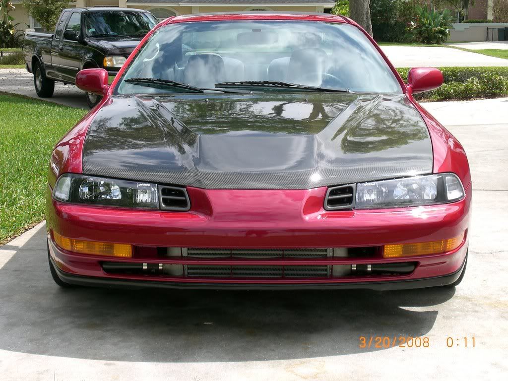
Honda Prelude Forum banner

h23 rebuild

59K views 348 replies 39 participants last post by  g-gameslude  
#1 · (Edited)
Here she is.
Image

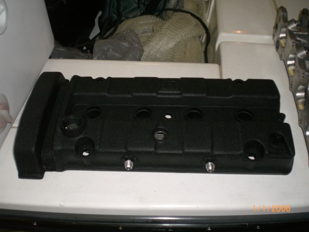
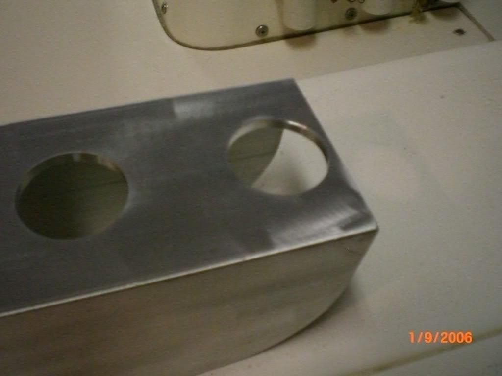
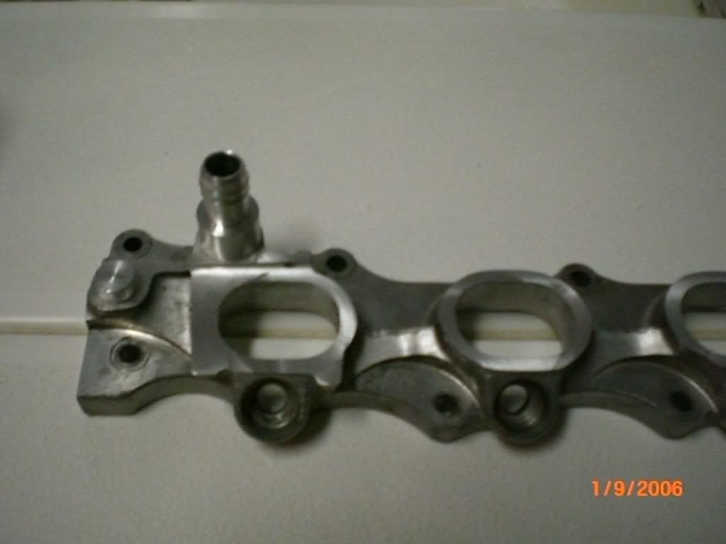
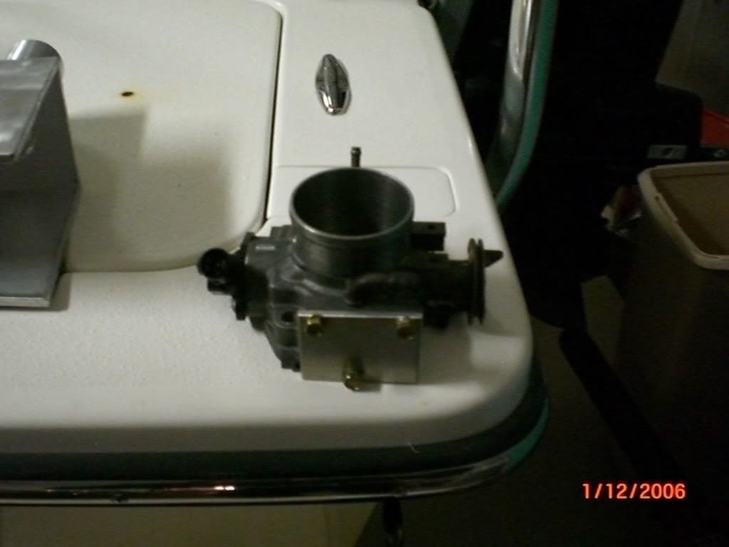
I am rebuilding my motor because my oil cooler line split open at 7,000 rpm. The motor is still in the car but on its way out soon. Damage is unknown but if I had to guess its a spun rod bearing. While I have been slowly pulling the motor I have been working on some side projects. They are a custom carch can setup, wire tuck, new recirculated downpipe and a custom intake manifold. Who knows I might even throw in some custom spec crower cams toward the end of the build. More to come soon and yes there will be lots of detailed pictures and specs on everything I do for all to learn.

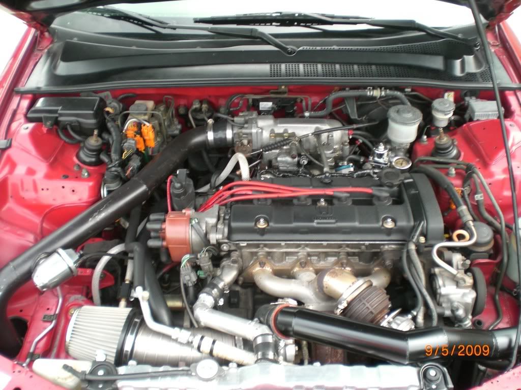
My seriously injured motor.
Image


Performance
Engine
Je pistons 8.5:1 custom
Je rings low tension moly coated
Eagle h22 rods
Darton iron sleeves
Balanced rotating assembly
Stainless steel o-ring set in sleeves
Full port and polish
3 angle valve job
Swirl polished valves
JG valve springs good for 8,200 rpm
AEM cam gears
2,300 lb pressure plate and 6 puck ceramic disk clutch
Clutchmasters 9lb flywheel
c-n-s aluminum radiator
r5671a-8 plugs .028 gap
Walbro 255 fuel pump
Ari fuel pressure regulator with liquid filled gauge
4” intake with K-n-N filter
Custom 3” exhaust with apex N1 and flex pipe aluminized steel
Bored stock throttle body 64mm
Xs Engineering t04x/t3 turbo
Xs Engineering silvia core intercooler 20”x12x3
Greddy profec b electronic boost controller
Greddy turbo timer
HKS ssbov
HKS gt wastegate
SFP turbo manifold
2.5” intercooler piping
3” downpipe
MSD 1006cc injectors
P72 ecu chipped with ectune
Gm 3 bar map sensor
Prodrive modified oil pump with billet steel gear
Prothane motor mounts
Egr eliminated
Balance shafts eliminated
Secondary butterflies removed
 
#4 ·
the motor will still crank up and run but there is a tick in the block. when the oil line split at 7,000 rpm it dumped out all 7 quarts of oil. 7,000 rpm + no oil = fucked bottom end.
 
#5 ·
i am done with my catch can setup. today i test fitted it and it fits great here are a couple pictures.

lines and push lock fittings:
Image


valve cover wrinkle painted and fittings:
Image


catch can 2.5 quart capacity:
Image


Image


Image


The motor is almost there. all that is left is the cv shafts and 4 motor mounts and it will be on a stand. also a start on my wire tuck.

Image


Here is the start of my custom intake manifold. i have spent weeks researching intake manifold theory and reviewing many other designs. i finally decided on a milled stock flange, 3.6 litre plenum, 4.5" runners and a 70mm throttle body. you can kind of get the idea from the pictures.

Image


Image


Image


You can see where the plenum will be cut.
Image


1.625" I.D. 1.9" O.D. runner pipe
Image


I still have to add a water outlet neck and weld in the egr plug to the flange.
Image


Image


I know many others have much nicer custom high dollar components on their prelude. keep in mind i am making all of my custom parts by my self in my garage on a pretty reasonable budget.
 
#6 ·
I made some more progress on the intake manifold. i hacked up my upper plenum to get the throttle body flange. i would have made one but this is easier and i could plug in for the IACV vacuum source.

Image


Image


since it would almost be impossible to mount the IACV on the new plenum i decided to fab up a remote mount. I will weld a mounting tab or something to it later.

Image


Image
 
#10 ·
There will be plenty of more custom parts to be made. The list is currently catch can setup, traction bar setup, intake manifold, downpipe and maybe a stainless tubular manifold. I just hate how weak the aftermarket parts world is for the h23 motor. Oh well, it looks like i will just have to make all of my own parts. Its more satisfying that way.

By the way, all of the parts for the intake manifolld should be done on saturday evening and I will probably start welding it together on sunday. You can expect photos by monday for sure.
 
#11 ·
Fabrication update: I decided to step up my game a little bit. A friend of mine has a mill and a lathe at his house so I decided to take full advantage. I cut the plenum's final shape and it is test fitted and ready for the lid to be welded on. We machined bores in the plenum floor to a 1.872" size. You will notice that the tops of the runners also have a 1.872" register machined at the tops of them for a nice and tight press fit. The registers are exactly .233" long so the fit exactly flush with the floor of the plenum. They are also radiused so they are smooth flowing and require no inside cleanup.

We also machined a double barbed water neck to replace the stock one an to delete the two additional water ports for the iacv. They would be a pain in the ass to retain for relocating the iacv to below the new intake manifold because I want it hidden. It also does not get that cold in Florida. Finally I gave all components a light polish prior to final assembly. Now its time for pictures.

Image


Image


Image


Image


Image


Image


Image
 
#12 ·
I still have to fly cut the runners level with the flange but you can see what it is going to look like with the runners pressed in.

Image


Image


Image


Image
 
#14 ·
Moar to come soon. I just found out that my girlfriend has been holding out on me. At her work in the shop they have a mandrel bender that I can use for free. So, now I am redesigning my runners to be 9" + to move my power band lower. Pictures to come in the next two days.
 
#15 ·
Minor update: While my girlfriends boss is takeing his time to bend me 4-180 degree J bends I did a little work at the house today. I made a fast idle block off plate for the throttle body, fabbed up a bracket to hold the throttle cable, and welded my throttle body flange to a plate that will weld to the plenum opening. The flange is welded inside and out to seal the iacv port and then hand blended for a smooth flow. Pics are kind of shitty quality.

Image


Image


Image


Image
 
#16 ·
Well I got bad news today, my g/f said they cannot bend 6061 aluminum pipe. She gave me this back. Apparently this was their best attempt.

Image


Here is what I got done after work today. I am expecting to be finished some time between sunday and wednesday depending on work.

Image


Image


Image


Image
 
#17 ·
I layed down tome tig welds today. They might not be the best looking welds but they are solid with good penetration. You must also keep in mind I have been tig welding for 9 months and tig welding aluminum for the past two. I will not be able to do any more work until next weekend since there has been a death in my friends who has been doing machine work.

Image


Image
 
#19 ·
That is how it has to sit for mounting the throttle cable. It will not affect the function. If you notice it sits how it does on a stock manifold with the bottom facing the runners.
 
#20 ·
wow, that custom manifold is sexy! I can't wait to see the finished product
 
#21 ·
I am fly cutting the runners saturday so the manifold won't sit on the rear motor mount. Im hoping to not even have to redo my cold side intercooler pipe. I will be welding the whole thing up this weekend so stay tuned.
 
#25 ·
Custom made IM, nice project. Good luck on finding a shop that can bent that kind of pipe, I didn't see the material being a problem. But then again all it probably wants to do is crimp instead of bend. I may be talking out of my ass on this one but would evenly heating the pipe up at a lower temp ( 150 f to 250 f ) help keep the bend smooth? Just a thought.
 
#26 ·
The only reason that I even tried it was because it was free. Oh well, I will just have to do some refitting to make my current design fit perfectly. Any ideas on final finish? I was thinking a light polish and then anodising it black so it will look like a black pearl.